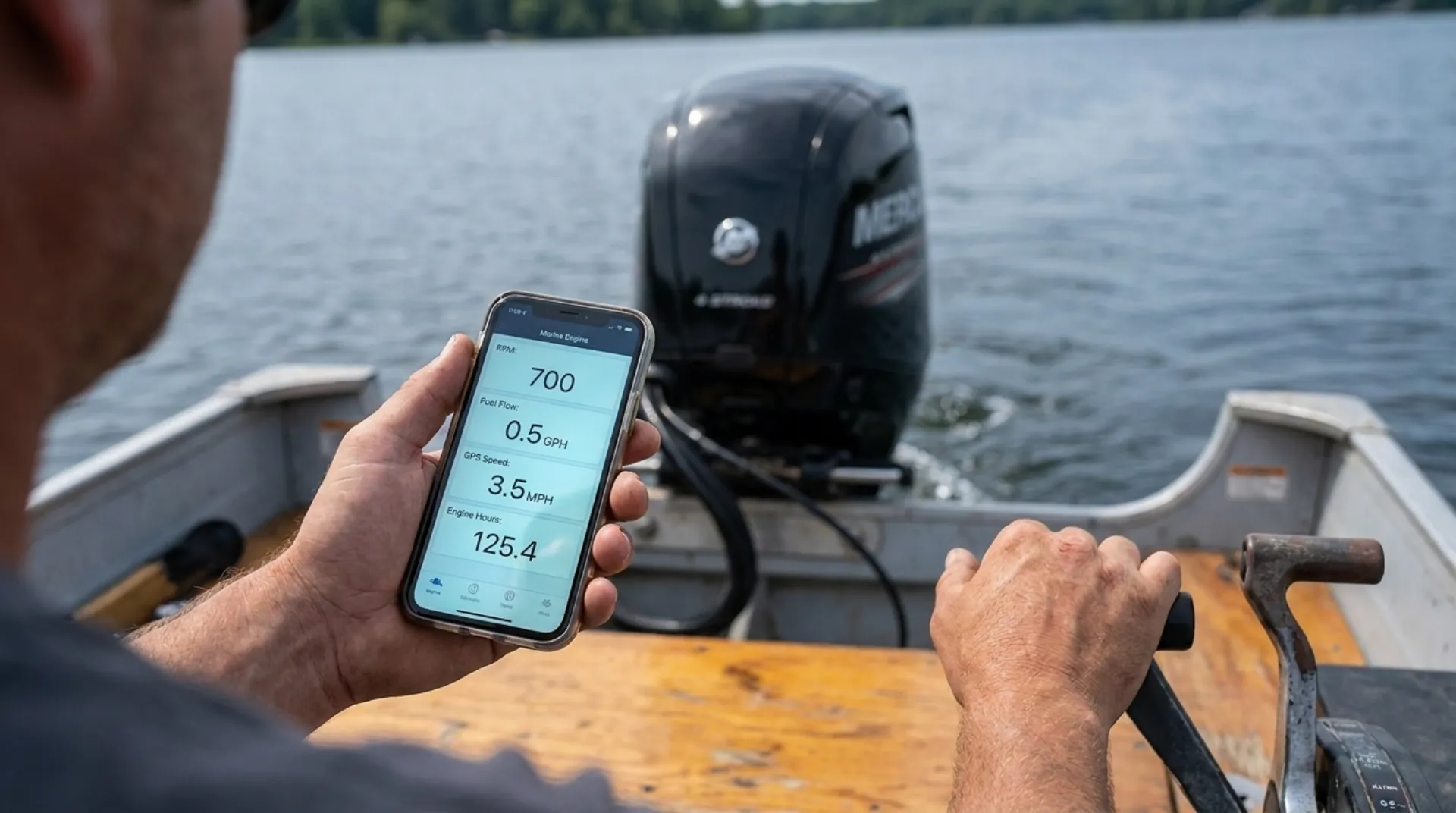
Quick answer: First identify the format on your screen. A single number or text label may come from Mercury's March 2007 legacy VesselView list. A two-part number such as 621-5 is a Universal Fault Code, or UFC, that must be matched to the correct engine-family publication....
Quick answer: First identify the format on your screen. A single number or text label may come from Mercury's March 2007 legacy VesselView list. A two-part number such as 621-5 is a Universal Fault Code, or UFC, that must be matched to the correct engine-family publication. This page includes Mercury's full 130-pair UFC set for the 2018-and-newer 3.4L V6 and 4.6L V8 platform as published in November 2021, plus a clearly labelled legacy VesselView reference. It is not a universal list for every Mercury outboard.
If the display shows low oil pressure, oil-pump failure, an active overheat, fuel leakage or overflow, loss of steering, or a gear that does not match the control command, skip the lookup and follow the stop-now guidance below. If the table does not resolve the alert, submit the photo and serial number at hbw.wiki/service.
This is the code-number companion to our Mercury beep and alarm guide. The horn tells you the alert class on supported systems; the screen identifies the actual fault. Both strategies vary by engine family and year.
Before You Use Either Table
- Photograph the whole alert first. Capture both numbers, all text, the affected engine, engine hours, and whether the display calls it active or history.
- Use the serial number. Mercury fault support changes by PCM calibration, model, year, controls, and connected modules. The exact Owner's Manual remains the operator authority.
- Treat the named circuit as a clue, not a parts order. A sensor code can be caused by the sensor, wiring, supply voltage, connector, or the condition being measured.
- Do not combine the two tables. A single legacy ID and a modern two-part UFC are different systems.
- Do not use a truck-code database. Use the product-specific Mercury table for the full pair shown on your display.
Which Mercury Code Format Are You Seeing?
| What the display shows |
Start here |
Important scope |
| Text such as Water in Fuel or a single number such as 23 |
Legacy VesselView table |
Mercury 90-898279, March 2007; mixed product, calibration-dependent |
| Two numbers separated by a dash, such as 621-5 |
Modern V6/V8 UFC table |
Mercury 90-8M0182076, November 2021; only the listed 3.4L V6 and 4.6L V8 platform |
| Horn only, with no code display |
Mercury beep and alarm guide |
Horn patterns vary by family, year, and rigging |
| Plain-language alert in the Mercury Marine app |
Record the exact text and any number |
SmartCraft Connect Mobile shows live data and fault notifications; it does not replace serial-specific service data |
Modern UFC Table: 2018-and-Newer 3.4L V6 and 4.6L V8
This table is scoped to Mercury diagnostic publication 90-8M0182076, November 2021, Section 4A, for PCM 112 outboards beginning at serial number 2B529482:
- 175 V6, 175 V6 Pro XS, 200 V6, 200 V6 SeaPro, and 225 V6
- 200 V8 Pro XS; 225 V8 Pro XS and SeaPro; 250 V8, Pro XS, SeaPro, and 250R; 300 V8, Pro XS, SeaPro, and 300R
These are 2018-and-newer applications in that publication. Not every listed pair applies to every model or control configuration. The table identifies the documented component or condition; it does not replace Mercury's official action, causes, tests, or repairs.
| UFC pair(s) |
Documented component or condition |
Manual page(s) |
| 101-16 / 102-16 / 103-16 / 104-16 |
Ignition circuits 1-4: PCM output-control fault |
4A-3 to 4A-5 |
| 201-16 / 202-16 / 203-16 / 204-16 / 205-16 / 206-16 / 207-16 / 208-16 |
Fuel-injector circuits 1-8: PCM output-control fault |
4A-6 to 4A-9 |
| 301-24 / 301-25 |
Throttle-position sensor A input above or below valid limit |
4A-9 |
| 302-24 / 302-25 |
Throttle-position sensor B input above or below valid limit |
4A-10 |
| 311-6 |
Throttle-position sensors A and B faulted |
4A-10 |
| 331-6 |
Throttle-position sensors A and B disagree |
4A-10 |
| 341-6 / 342-6 |
Throttle-position sensor A or B adaptation fault |
4A-11 to 4A-12 |
| 401-24 / 401-25 |
Time-sampled manifold-pressure input above or below valid limit |
4A-12 to 4A-13 |
| 402-24 / 402-25 |
Angle-sampled manifold-pressure input above or below valid limit |
4A-13 |
| 404-6 / 405-6 |
Manifold-pressure and throttle-position signals disagree |
4A-14 |
| 407-17 |
Manifold-pressure barometric reading outside expected range |
4A-15 |
| 431-21 |
Oil pressure below the specified threshold |
4A-15 |
| 431-24 / 431-25 |
Oil-pressure sensor input above or below valid limit |
4A-16 |
| 511-24 / 511-25 |
Intake-air-temperature input above or below valid limit |
4A-17 |
| 521-20 |
Starboard engine-coolant temperature above normal |
4A-17 |
| 521-24 / 521-25 |
Starboard coolant-temperature sensor input above or below valid limit |
4A-18 |
| 531-24 / 531-25 |
Oil-temperature sensor input above or below valid limit |
4A-19 |
| 572-24 / 572-25 |
Bank 1 exhaust-gas-temperature sensor input above or below valid limit |
4A-19 to 4A-20 |
| 601-4 / 601-5 |
Sensor-supply voltage A higher or lower than expected |
4A-20 to 4A-21 |
| 602-4 / 602-5 |
Sensor-supply voltage B higher or lower than expected |
4A-21 to 4A-22 |
| 603-4 / 603-5 |
Sensor-supply voltage C higher or lower than expected |
4A-23 |
| 621-4 |
Valid system voltage higher than expected |
4A-23 |
| 621-5 |
Valid system voltage lower than expected |
4A-24 |
| 711-6 |
Oil-level sensor fault |
4A-24 |
| 711-12 |
Oil-level sensor invalid or disabled under present conditions |
4A-25 |
| 711-19 |
Oil-level test could not run, so level could not be determined |
4A-25 |
| 711-24 |
Oil-level sensor input above valid limit |
4A-25 |
| 713-21 |
Crankcase oil level below the specified threshold |
4A-26 |
| 821-1 / 821-27 |
Wideband oxygen-sensor output circuit open/high resistance or short/low resistance |
4A-26 to 4A-27 |
| 822-4 / 822-5 / 822-16 |
Wideband oxygen-sensor heater high, low, or output-control fault |
4A-27 to 4A-28 |
| 902-4 / 902-5 |
Port short-term fuel-trim correction higher or lower than expected |
4A-29 |
| 1012-24 / 1012-25 |
Engine trim-position input above or below valid limit |
4A-30 |
| 1021-24 / 1021-25 |
Shift-actuator position sensor A input above or below valid limit |
4A-31 |
| 1023-24 / 1023-25 |
Shift-actuator position sensor B input above or below valid limit |
4A-32 |
| 1024-6 |
Shift-actuator position sensors A and B disagree |
4A-33 |
| 1025-6 |
Both shift-actuator position sensors faulted |
4A-33 |
| 1051-23 |
Camshaft synchronization state fault |
4A-33 |
| 1052-6 |
Crankshaft or camshaft trigger fault |
4A-34 |
| 1061-24 / 1061-25 |
Mechanical throttle-demand sensor A input above or below valid limit |
4A-34 to 4A-35 |
| 1062-24 / 1062-25 |
Mechanical throttle-demand sensor B input above or below valid limit |
4A-35 to 4A-36 |
| 1063-24 / 1063-25 |
Mechanical shift-demand sensor A input above or below valid limit |
4A-36 to 4A-37 |
| 1064-24 / 1064-25 |
Mechanical shift-demand sensor B input above or below valid limit |
4A-37 |
| 1071-6 / 1072-6 |
Mechanical throttle-demand sensor A or B adaptation fault |
4A-38 |
| 1073-6 |
Mechanical throttle-demand sensors A and B disagree |
4A-39 |
| 1074-6 |
Both mechanical throttle-demand sensors faulted |
4A-39 |
| 1077-6 |
Mechanical shift-demand sensors A and B disagree |
4A-40 |
| 1078-6 |
Both mechanical shift-demand sensors faulted |
4A-40 |
| 1108-25 |
Water detected in the fuel system |
4A-40 |
| 1109-23 |
Emergency-stop circuit active |
4A-41 |
| 2011-23 |
Engine Guardian active and limiting power |
4A-41 |
| 2021-23 |
Guardian active because of oil temperature |
4A-42 |
| 2032-23 |
Guardian active because of exhaust-system temperature |
4A-42 |
| 2051-23 |
Guardian active because of low oil pressure |
4A-43 |
| 2081-23 |
Guardian active because of engine overheat |
4A-43 |
| 2091-23 |
Guardian active because of excessive engine speed |
4A-44 |
| 2092-23 |
Engine speed above its neutral limit |
4A-44 |
| 2101-23 |
Guardian active because the helm module requested a power limit |
4A-45 |
| 2111-23 |
Guardian active because of battery voltage |
4A-45 |
| 2124-20 |
Exhaust-manifold temperature above normal |
4A-45 |
| 3002-16 |
Active-exhaust-valve output-control fault |
4A-46 |
| 3012-6 / 3013-6 / 3014-6 |
Electronic throttle lost control, has an output fault, or is sticking |
4A-46 to 4A-47 |
| 3031-6 / 3032-6 |
Electronic shift commanded position differs from actual position, or control is lost |
4A-48 |
| 3033-6 / 3034-6 |
Electronic shift could not adapt in reverse or forward |
4A-49 |
| 3037-6 |
Electronic shift control timed out |
4A-50 |
| 3039-23 |
Reverse gear unavailable; a reverse command may produce forward gear |
4A-50 |
| 3049-16 |
Hydraulic-shift output-control fault |
4A-51 |
| 3061-16 |
Fuel-pump output-control fault |
4A-51 |
| 3152-16 |
Warning-horn output-control fault |
4A-52 |
| 3171-16 |
Starter output-control fault |
4A-53 |
| 3181-16 / 3182-16 |
Trim-up or trim-down output-control fault |
4A-52 to 4A-53 |
| 4001-6 / 4002-6 / 4003-6 |
Demand, shift, or helm-module crosscheck fault |
4A-54 to 4A-55 |
| 4004-6 |
CAN X document 1 state-of-health fault |
4A-55 |
| 4005-6 |
CAN P document 2 state-of-health fault |
4A-56 |
| 4006-6 / 4007-6 / 4008-6 / 4009-6 |
CAN P or CAN X document state-of-health fault |
4A-56 to 4A-58 |
| 4010-6 |
CAN X document 11 state-of-health fault |
4A-58 |
| 4011-23 |
CAN-bus authentication timeout |
4A-58 |
| 4012-6 |
CAN P and CAN X state-of-health faults |
4A-59 |
| 4013-23 |
Watchdog active |
4A-59 |
| 4014-6 / 4016-6 |
Watchdog-module or watchdog-data crosscheck fault |
4A-60 |
| 4501-23 |
Security device missing |
4A-61 |
| 4502-23 |
Security system locked |
4A-61 |
| 4503-23 |
Security system in setup mode |
4A-61 |
| 4602-23 |
Low system voltage blocking other fault evaluation |
4A-62 |
There are 130 enabled UFC pairs in that scoped 2021 publication. The 2018 version lists the same 130 enabled pairs and also shows 0-0 as a no-active-fault sentinel. Do not count 0-0 as an enabled fault or apply this table to a different Mercury family.
What the UFC Suffix Means in This V6/V8 Publication
The number after the dash describes how the named component, value, or state failed. These short definitions are scoped to this publication; always interpret the complete pair.
| Suffix |
Meaning in the scoped table |
| 1 |
Output circuit open or resistance too high |
| 4 |
Valid value higher than expected |
| 5 |
Valid value lower than expected |
| 6 |
Device, calculation, adaptation, or process fault |
| 12 |
Device invalid or disabled under present conditions |
| 16 |
Output-control fault detected by the controller |
| 17 |
Signal outside the expected range |
| 19 |
Test could not run under present conditions |
| 20 |
Temperature higher than normal |
| 21 |
Value below a specified threshold |
| 23 |
A documented state or condition exists |
| 24 |
Sensor input above its valid limit |
| 25 |
Sensor input below its valid limit |
| 27 |
Input circuit shorted or resistance too low |
That is why 621-5, not 621-25, is the low-system-voltage pair in this V6/V8 publication. The same suffix does not give you permission to invent a component meaning that is absent from the correct Mercury table.
Legacy VesselView Fault IDs: March 2007 Mixed-Product List
Mercury's VesselView operation manual 90-898279, March 2007, printed a single-number fault list through 247. Mercury's own note is the most important part: the displayed faults are determined by PCM calibration, not every fault is used on every engine, the information was accurate at the printing date, and it could change.
This is not an outboard-only master list. It mixes outboard, MerCruiser, DTS, diesel or transmission, drive-lube, hydraulic-shift, and legacy supercharged-Verado items. The grouped descriptions below preserve the display-level meaning without inventing cylinder assignments where the VesselView manual only repeats a generic label.
| Legacy ID(s) |
March 2007 display meaning |
Scope note |
| 1 |
Critical high battery voltage |
Mixed-product VesselView |
| 2 |
Critical low battery voltage |
Mixed-product VesselView |
| 3 |
Low cooling-water pressure |
Application-dependent |
| 4 |
Compressor overtemperature |
Legacy compressor-equipped application |
| 5-6 |
Critical throttle-position control fault |
DTS/application-dependent |
| 9 |
Engine Guardian active; power limited |
Root fault appears separately |
| 10-11 |
Knock sensor or knock-prevention fault |
Application-dependent |
| 12 |
Low engine-oil pressure |
Four-stroke/inboard application as equipped |
| 13 |
Remote two-stroke oil tank low |
Oil-injected two-stroke |
| 14 |
Engine-mounted two-stroke oil tank critically low |
Oil-injected two-stroke |
| 15-16 |
Manifold absolute-pressure sensor fault |
Application-dependent |
| 17 |
Excess air in idle state |
Application-dependent |
| 18 |
Oil-pump fault |
Oil-injected two-stroke |
| 19 |
Engine overspeed |
Application-dependent |
| 20-21 |
Engine overtemperature |
Application-dependent |
| 22 |
Warning-horn output fault |
Application-dependent |
| 23 |
Water in fuel |
Application-dependent |
| 24-35 |
Direct/air injector fault; twelve generic entries |
Legacy DFI display list; no cylinder mapping in this table |
| 36-37 |
Water-pressure sensor fault |
Application-dependent |
| 38 |
Break-in strategy remaining |
Legacy PCM strategy |
| 39-40 |
Engine-air-temperature sensor fault |
Application-dependent |
| 41-42 |
Air-compressor-temperature sensor fault |
Compressor-equipped application |
| 43-54 |
Ignition-coil fault; twelve generic entries |
Cylinder mapping depends on service data |
| 59-70 |
Fuel-injector fault; twelve generic entries |
Cylinder mapping depends on service data |
| 75-76 |
Fuel-level sender fault |
Vessel/tank input |
| 77 |
Crank/cam encoder fault |
Application-dependent |
| 78-79 |
Jack-plate position sensor fault |
Boats equipped with jack plate input |
| 80 |
Critical main-power-relay fault |
Application-dependent |
| 81 |
Main-power-relay backfeed |
Application-dependent |
| 82-83 |
Oil-tank level sensor fault |
Oil-tank-equipped application |
| 84-85 |
Engine-oil-pressure sensor fault |
Application-dependent |
| 89-90 |
Engine-oil-temperature sensor fault |
Application-dependent |
| 91 |
Engine-oil temperature high |
Application-dependent |
| 92 |
Paddle-wheel speed sensor fault |
Vessel sensor |
| 93-94 |
Pitot/speed-pressure sensor fault |
Vessel sensor |
| 95-96 |
Coolant-temperature sensor fault |
Application-dependent |
| 97-98 |
Trim-tab position sensor fault |
Trim-tab-equipped vessel |
| 99-100 |
Trim-tab controller fault |
Trim-tab-equipped vessel |
| 101 |
Critical SmartCraft communication fault |
Network/application-dependent |
| 102 |
SmartCraft communication fault |
Network/application-dependent |
| 103 |
Critical SmartCraft communication fault |
Network/application-dependent |
| 104-105 |
Seawater-temperature sensor fault |
Vessel sensor |
| 106-108 |
Critical shift-actuator fault |
DTS/shift application |
| 109 |
Shift-actuator fault |
DTS/shift application |
| 110 |
Shift-switch fault |
Shift application |
| 111-112 |
Coolant-temperature sensor fault |
Application-dependent |
| 113-114 |
Trim-tab sensor fault |
Trim-tab-equipped vessel |
| 115-116 |
Trim-tab control fault |
Trim-tab-equipped vessel |
| 117 |
Starter-solenoid/output fault |
Application-dependent |
| 118-119 |
Steering-angle sensor fault |
Steering-equipped application |
| 120-131 |
Throttle-position sensor fault; multiple channels |
Application-dependent |
| 132 |
Crankshaft-position sensor fault |
Application-dependent |
| 133 |
Critical low sensor-supply voltage |
Application-dependent |
| 134-135 |
Engine overspeed |
Application-dependent |
| 136-137 |
Boost-bypass valve fault |
Legacy supercharged application |
| 138 |
Engine-control-unit fault |
Application-dependent |
| 148 |
Shift-controller fault |
DTS/shift application |
| 149 |
Critical electronic-throttle-controller fault |
Electronic throttle application |
| 150 |
Critical SmartCraft communication fault |
Network/application-dependent |
| 151 |
Critical fuel-pump fault |
Application-dependent |
| 152 |
Idle-air-control valve fault |
Application-dependent |
| 153 |
Low drive-lube level |
Sterndrive, not an outboard fault |
| 154 |
Excessive calculated airflow |
Application-dependent |
| 155-157 |
Secondary manifold-pressure sensor fault |
Application-dependent |
| 158-160 |
Port exhaust-manifold temperature sensor fault or high temperature |
Inboard/sterndrive application |
| 163 |
Critical SmartCraft communication fault |
Network/application-dependent |
| 169-170 |
Engine-oil-pressure sensor fault |
Application-dependent |
| 171-172 |
Engine Guardian active; power limited |
Root fault appears separately |
| 173-174 |
Fuel pressure high or low |
Application-dependent |
| 175 |
Knock system not functioning |
Application-dependent |
| 176 |
Critical shift fault |
Shift application |
| 177-179 |
Starboard exhaust-manifold temperature sensor fault or high temperature |
Inboard/sterndrive application |
| 180-183 |
Throttle-position sensor fault or disagreement |
Application-dependent |
| 184-185 |
Trim relay fault |
Trim-equipped application |
| 186-190 |
Critical SmartCraft communication fault; multiple modules |
Network/application-dependent |
| 191-192 |
Tank 2 level sender fault |
Vessel/tank input |
| 193-194 |
Shift fault |
Shift application |
| 195 |
Thermostat fault |
Application-dependent |
| 196 |
Transmission overtemperature |
Inboard/transmission application |
| 197-199 |
Supercharger outlet-temperature sensor fault or high temperature |
Legacy supercharged application |
| 200 |
Boost-bypass valve fault |
Legacy supercharged application |
| 201-203 |
Engine-temperature sensor fault or overtemperature |
Application-dependent |
| 204-206 |
Block-temperature sensor fault or overtemperature |
Application-dependent |
| 207-208 |
Fuel-lift-pump fault |
Application-dependent |
| 209 |
Critical low engine-actuator voltage |
Electronic-control application |
| 210 |
Neutral overspeed |
Electronic-control application |
| 211 |
Reverse overspeed |
Shift application |
| 212 |
Start sequence aborted |
Electronic-start application |
| 213 |
Fuel overflow into vent system |
Fuel-system application |
| 214 |
Boost-bypass valve fault |
Legacy supercharged application |
| 215-216 |
Critical SmartCraft communication fault |
Network/application-dependent |
| 217 |
Low sensor-supply voltage |
Application-dependent |
| 218 |
Critical SmartCraft communication fault |
Network/application-dependent |
| 219 |
Shift command fault; control requested to neutral |
DTS/shift application |
| 220 |
Fuel overflow into vent system |
Fuel-system application |
| 221 |
Fuel-lift-pump float-switch fault |
Fuel-system application |
| 222 |
Fuel-lift-pump fault |
Fuel-system application |
| 223-225 |
Piston-cooling oil-jet pressure or sensor fault |
Application-dependent |
| 226 |
Critical SmartCraft communication fault |
Network/application-dependent |
| 227-232 |
Shift-pressure sensor fault |
Hydraulic-shift application |
| 233 |
Shift-system fault |
Shift application |
| 234 |
Shift pressure high |
Hydraulic-shift application |
| 235 |
Shift fault; control requested to neutral |
Shift application |
| 236 |
Emergency-stop circuit active |
Application-dependent |
| 237 |
Power limited by knock system |
Guardian response |
| 238 |
Overspeed in trailer position |
Trim/engine application |
| 239 |
Underwater impact detected |
Application-dependent |
| 240 |
Critical low battery voltage |
Mixed-product VesselView |
| 241 |
Charge-air temperature high |
Legacy supercharged application |
| 242 |
Fuel-purge-valve fault |
Application-dependent |
| 243-244 |
Trim-tab sensor fault |
Trim-tab-equipped vessel |
| 245 |
Shift-switch fault |
Shift application |
| 246 |
Power limited by supercharger overtemperature |
Legacy supercharged application |
| 247 |
Power limited by knock system |
Guardian response |
If your single-number code is absent, do not fill a gap with a neighbouring meaning. Mercury left gaps in this printed list, and connected modules can generate alerts outside it.
Stop-Now Conditions
The code table identifies the alert. What you observe determines the safest immediate response.
Low Oil Pressure
Stop the engine. Check the oil level using the engine position and procedure in the serial-number-specific manual. If the level is correct or the warning persists, do not continue running. A sensor-circuit alert does not prove that actual oil pressure is safe.
Two-Stroke Oil-Pump Fault
Stop and do not restart. Mercury's SC1000 documentation warns that an electrical oil-pump fault means lubricating oil is not being supplied.
Fuel Leak or Fuel-Overflow Warning
Stop the engine and do not restart it. Keep smoking, flames, sparks, and other ignition sources away. Any sign of fuel leakage requires repair before further operation. Do not try to “head in” under engine power.
Overheat or No Cooling-Water Flow
Reduce throttle immediately. When safe, shift to neutral and stop the engine. Inspect the cooling-water inlets only with the engine off. If water flow was absent or intermittent, or the warning remains after the checks allowed by your manual, do not continue running.
DTS, Shift, Steering, or CAN Fault
Reduce power and follow the exact display instruction. Do not force the control or linkage, and do not assume neutral or reverse remains available. If indicated gear does not match the command, neutral cannot be confirmed, steering is affected, or a critical communication alert persists, stop as soon as safe and arrange assistance. Any restart procedure must be specific to that engine, control system, and fault.
Voltage Warning
Turn off nonessential electrical loads and keep control of the boat. Touch battery connections only after key-off and electrical isolation. Do not universally raise RPM: some current systems can increase idle automatically during low voltage. If the alert is critical, Guardian is active, or throttle, shift, steering, or CAN operation is affected, stop safely and arrange assistance.
Active Fault, Display History, and Module History Are Different
An active fault is present now. A display history is the alert list stored by that display. A supported engine module can also hold diagnostic fault history and operating snapshots, but the available record varies by module and fault.
Photograph the exact code and text, affected engine, hours, horn pattern, and operating conditions before dismissing or deleting anything. Clearing a VesselView display's archived history clears that display list. It must not be described as erasing the PCM record a technician may read with CDS G3.
Likewise, do not assume every stored fault includes the same freeze-frame data. Mercury's current CDS G3 material describes fault history and a last-30-fault list only where supported.
How to Read the Alert on Common Mercury Displays
VesselView 403
Select View or press Enter to open the alert details. History is under Menu > Alarms. The 403 manual says an active fault clears after the cause is repaired and the engine passes its startup scan; do not generalize that exact behaviour to every VesselView generation.
VesselView 704
Open Tiles > Alerts > Engine alerts, then expand the alert for its description, severity, and code. Alert history is under Settings > Alerts. Closing the window is not an engine-module history clear.
SC1000 System Tach
The descriptive fault view shows location, component, detail, corrective action, and additional faults through MORE, ACTION, and NEXT on supported systems. Do not use Master Reset to chase an engine fault; it restores gauge defaults and erases gauge setup and calibration.
SmartCraft Connect Mobile and the Mercury Marine App
For fault work, the current app provides live engine data and fault notifications. Older VesselView Mobile hardware can also work with the current Mercury Marine app. The phone view does not replace CDS G3 module tests, adaptations, configuration, or serial-specific service information. See our SmartCraft Connect Mobile guide.
Dealer CDS G3
CDS G3 provides the supported module's diagnostic fault history, operating snapshots where available, state-of-health information, tests, configuration, and programming functions. It is the shop tool, not a reason to guess at a repair from a public table.
What Helps the Shop Start Faster
Before submitting a service request, collect:
- A clear photo showing the complete number and all display text.
- The engine serial number and which engine is affected on a multi-engine boat.
- Engine hours and whether the display says active or history.
- The horn pattern, including duration and whether it repeated.
- What the boat was doing: key-on, idle, accelerating, cruising, shifting, trimming, or restarting.
- Any recent battery, rigging, control, fuel-system, or service work.
- Whether Guardian limited power, water flow changed, steering changed, or indicated gear disagreed with the control.
Do not clear or repeatedly restart just to make the message disappear. Preserve the evidence and submit it at hbw.wiki/service.
Common Lookup Mistakes
- Calling the March 2007 1-247 list a current or outboard-only master list.
- Translating 621-25 as low voltage on every Mercury; the scoped V6/V8 publication uses 621-5.
- Reading a sensor name as proof the sensor itself failed.
- Treating Guardian as the root cause instead of the protective response.
- Applying one VesselView menu path or clearing behaviour to every display generation.
- Assuming closing a display alert clears the engine module's history.
- Assuming every stored fault includes identical freeze-frame data.
- Forcing a DTS control or trying a generic key cycle when gear or steering status is uncertain.
Sources